Make a device that will give me a light indicator of when the music is too loud from our building. MIT policy states that music
cannot be audible from outside. The sensor would be placed outside and the light would be placed inside.
Materials and software
Fusion 360
Eagle for circuit design (in Fusion)
Circuit board bill
MIC MEMS ANALOG OMNI -22DB
Xiao RP2040
Female and male jumper cables and pins
Hot Glue
Fusion Work
Need to make a simple board with surface mounted mic to connect to the xiao rp2040
I read the datasheet wrong the first time and did not have the right design
Additionally, I thought I could just not connect gain and ignore it, but in testing the board gave no responsivness
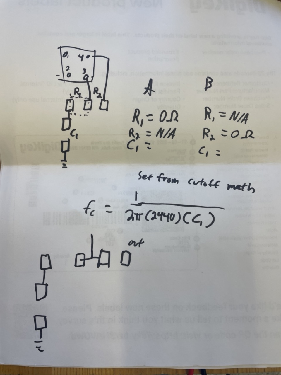
Redesigned board in order to have the option to connect gain depending on which 0 ohm resistor I soldered
Paper mock up
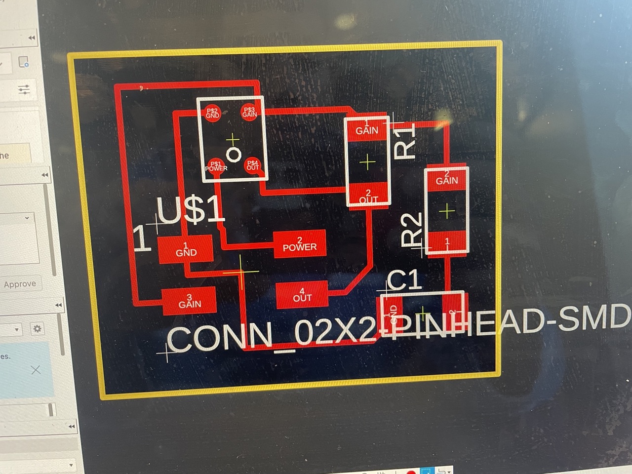
Updated board
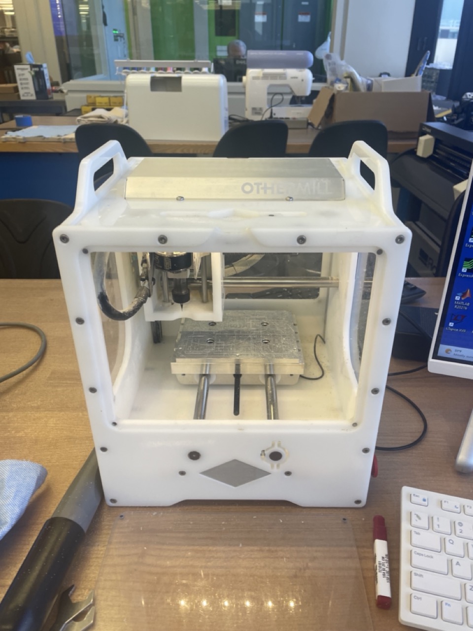
Circuit board mill
This part was pretty straight forward except for trying to put the right bit in the machine
It constantly switched on me and I had to keep changing it and then it would use the 1/64th bit for 2 seconds
If you're confused on what bit it is just grab a caliper and measure the bit
I learned how to start the board drilling in a different spot than the bottom left by changing the origin
Circuit board mill used
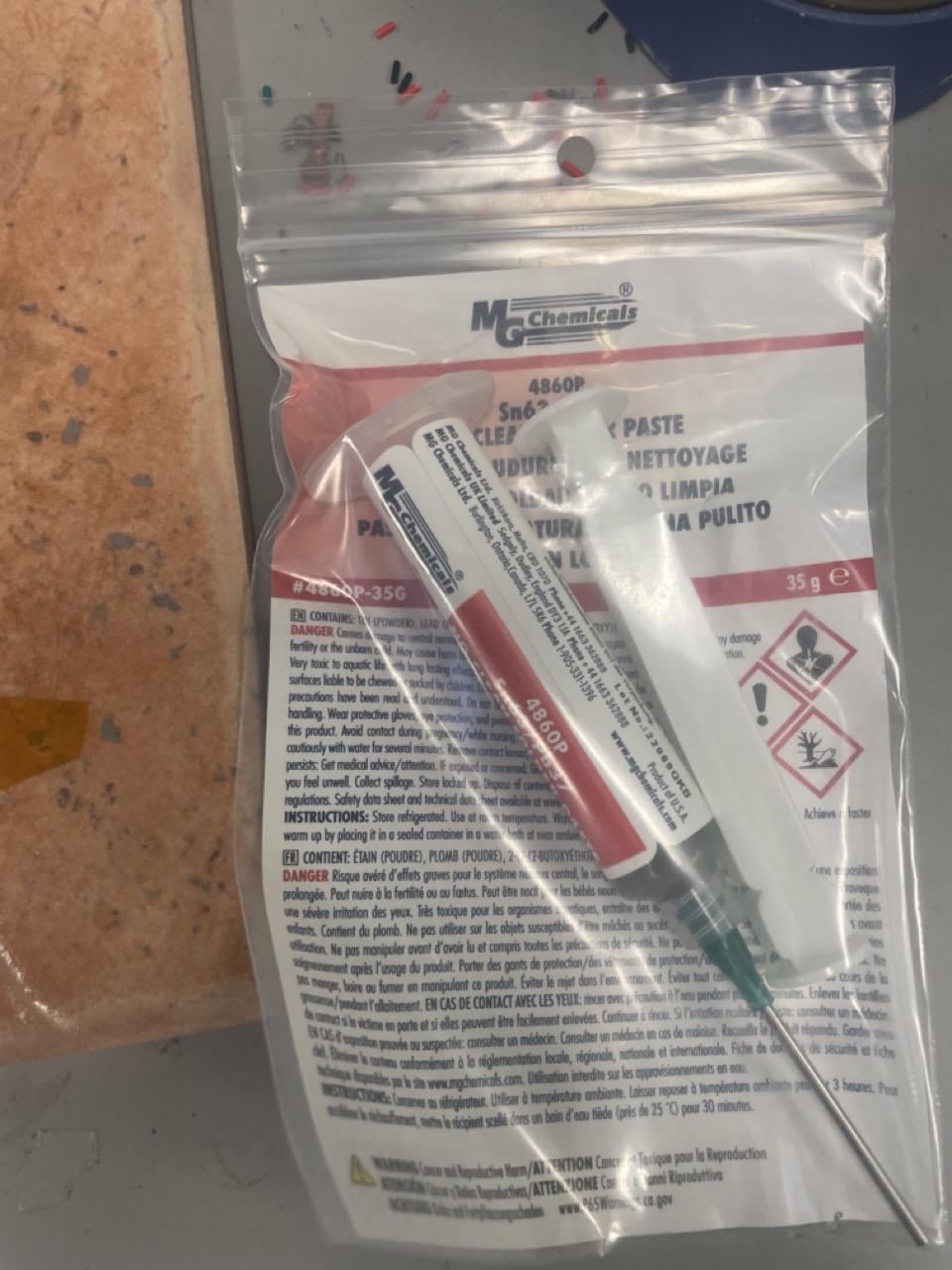
Soldering
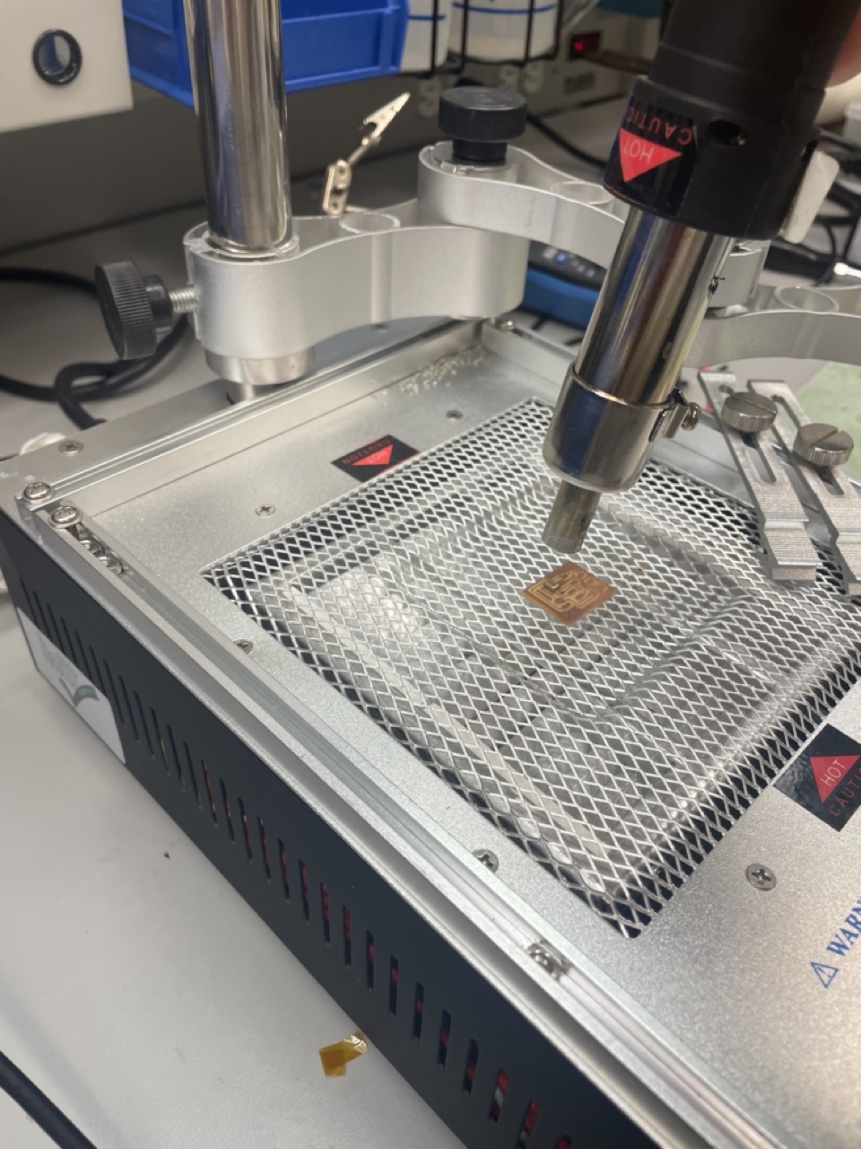
Because the mic was surface mounted I needed to learn how to solder with a hot air gun
This includes a hot air gun and a paste
You want to get a decent dot on all of your components because the solder shrinks considerably
I ended up liking this method a lot more than soldering by hand which took longer and more frsutration
I also learned theres a desoldering pinchers which will snip off the soldered component easily
*************
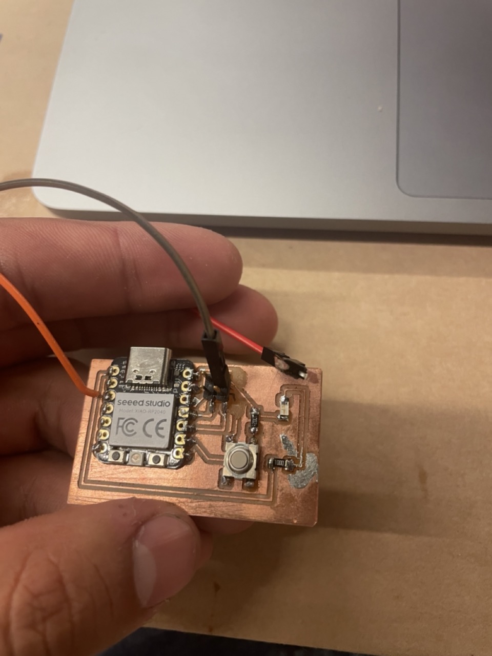
Separately I left my board in my backpack and pins broke so I had to hot glue female connectors to the board
This ended up being ok because my pinout for the board I was reusing WAS NOT COMPATIBLE WITH ANALOG so I had to jump a couple pins
Additionally I learned that I connected gain to a pin when it did not need to be but thankfully it did not break anything and just used the out
********
Also learned more about capacitors and frequency units cause I had to calculate the size of capacitor based off the datasheet equation.
Heat tray
Solder paste
Jerry rigged test board
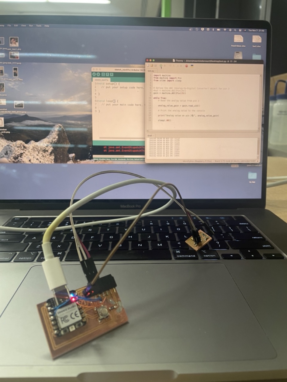
Analyzing Signals
I have never deal with analog signals before so I had to learn how to mess with them
To me I was just receiving a ton of random numbers from the pin and it oscilated extremely randomly
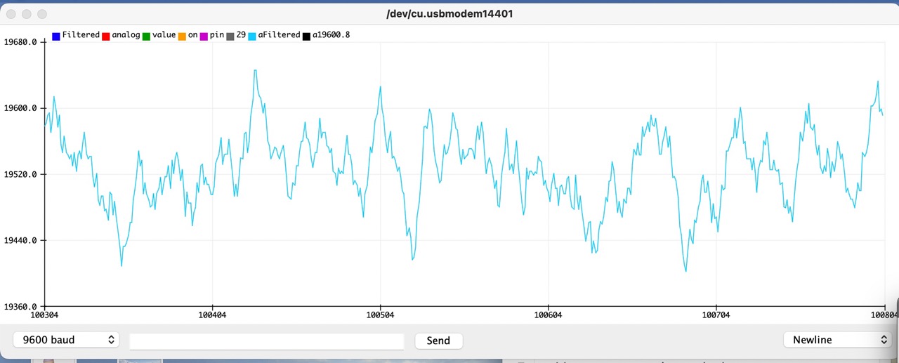
Part of the reason this happens is how often you sample and whether or not you filter the signal
Given that I am not a signal processing expert I just used a simple filter to average the last 10 values
After that I played with the average threshold and sampling frequency to get the right values for the EECS Lab
I eventually was able to get an led to start blinking when I blasted music from my speaker next to it but sitll needs tuning
New wired board plus tuning
Signals post filtering
        import machine
        from machine import Pin
        from utime import sleep

        # Define the ADC (Analog-to-Digital Converter) object for pin 29
        gain = machine.ADC(Pin(29))

        # Define the filter parameters
        filter_length = 10  # Number of samples to average
        filtered_values = [0] * filter_length

        # Define the LED on pin 26
        led = machine.Pin(26, machine.Pin.OUT)

        # Set the sound level threshold
        sound_threshold = 19600  # Adjust as needed

        while True:
            # Read the analog value from pin 29
            analog_value_gain = gain.read_u16()

            # Add the current reading to the filter buffer
            filtered_values.pop(0)
            filtered_values.append(analog_value_gain)

            # Calculate the average of the filtered values
            filtered_value_avg = sum(filtered_values) / filter_length

            # Print the filtered analog value to the console
            print("Filtered analog value on pin 29:", filtered_value_avg)

            # Check if the filtered value is above the sound threshold
            if filtered_value_avg > sound_threshold:
                # Turn on the LED on pin 26
                led.on()
            else:
                # Turn off the LED on pin 26
                led.off()

            sleep(0.1)
Conclusions
Started seeing what signal processing is like
Learned how to use solder paste
Understood that grabbing sensor and slapping it on board is not as straightforward as it seems. Well maybe not it will be hopefully
Don't put your precious board in your backpack
If you put jumpter cable make sure they are short and not long and dangling
Make boards for different data sheets is slowly getting more familiar